Radar basics

Driven by general wartime events and by the development of the air forces into important service providers, radar technology experienced a strong development spurt during World War II and was used in large numbers along the inner-German border during the " Cold War ". If the waves are bundled in a strong direction, the direction in which the object is located can also be determined. With the distance and direction values, the position of the object in relation to the place of origin is clearly determined.
Devices that determine this position using electromagnetic waves are called RADAR devices . This is an artificial word from the English-speaking world:
RAdio (Aim) Detecting And Ranging. Around the time of World War II the word "Aim" was added. However, it was later omitted again, since RADAR does not only affect flight destinations.
The distance is determined from the propagation time of the high-frequency transmission signal and the propagation speed C0. It actually measures a slant distance: the distance between the radar device and a flight target. (A calculation of the distance on earth is possible, but the flight altitude must be known.) However, since the outward and return journey must be taken into account, the following formula results: In air traffic control, the distance is given in "nautical miles", in air defense in kilometers.
Direction determination of a target:
Angle of the antenna at the time of reception. ( More precisely ... )
Radar devices usually work with very high frequencies. Reasons for this are:
- the rectilinear quasi-optical propagation of these waves,
- the high resolution (the smaller the wavelength , the smaller objects can be distinguished from each other
The term target distance (R range) is understood to be the distance between the radar device and the target. The target distance can be determined from the transit time of the radar signal from the transmitter to the target and back to the receiver.
If the respective transit time t is known, the distance R between any target and the radar system can be calculated with the help of this equation.
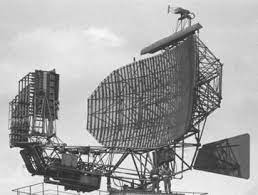
Radar antennas typically rotate horizontally to extend radar coverage over a large area. Angular values from 0° to 360° are assigned to this rotational movement. The reference direction is geographical north with a (side) angle of 0°. The azimuth angle is increased in a clockwise direction (direction of rotation of an all-around antenna). The azimuth can also be plotted clockwise relative to your course. This is a type of display that is often chosen on ships or in airplanes.
In order to precisely determine the azimuth angle , an exact measurement of the north direction is necessary. Older radar devices therefore have to be calibrated either magnetically or geographically using known terrain points. More modern radar devices take over this task themselves and determine the direction geographically north themselves with the help of the GPS satellites .
The elevation angle is counted positive above the horizon (0° elevation angle), negative below the horizon. The English term for elevation angle is Elevation (El).
Target height (or altitude) is the distance of a target above the earth's surface (height above ground). It is abbreviated with the letter H (height). The altitude can be calculated from the target distance R and the elevation angle ε.
With R for the hypotenuse and H for the opposite leg, the following results:
In relation to a real flight target, the target height cannot be calculated so easily, since
- the electromagnetic waves in the atmosphere undergo refraction at the air layer transitions (different densities) and
- the surface of the earth has a curvature.
Both factors are balanced in radar systems with integrated height calculation using complex formulas.
This formula for calculating the target height is used in the PRW-16: The individual formula sections mean:
- Target height without considering the curvature of the earth
- the influence of the curvature of the earth on the target height
- the influence of refraction in the atmosphere
- a temperature coefficient
The radar equation is used to show the physical relationships between the transmission power, the wave propagation and reception. it can also be used to assess the operational performance of radar systems.
Derivation of the radar equation
This results in the following formula for the non-directional power density Su:
If the radiation (with the same transmission power) is limited to a partial spherical surface by suitable measures, the power density increases in the direction of radiation. One speaks of an antenna gain. This gain is achieved through directed radiation of the energy. The directional power density is:
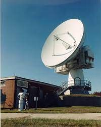
In reality, radar antennas are of course not "partially radiating" spherical radiators, but directional antennas (eg parabolic antennas or phased array antennas) with an antenna gain of 30 to 40 dB.
Target acquisition not only depends on the power density at the target location, but also on the limitation of how much of it is actually reflected back in the direction of the radar system. In order to be able to determine the usable reflected power, the reflecting area σ is required.
This variable, which is difficult to determine, depends on several factors. So it is initially obvious that a larger area reflects more power than a small area, in other words:
A jumbo jet offers more reflection surface than a sports aircraft with the same flight attitude. In addition, the reflecting surface depends heavily on the shape, surface finish and the materials used.
Summarizing what has been said so far, the reflected power Pr (at the target location) results from the power density Su , the antenna gain G and the very variable reflecting area σ :
At the radar antenna, the received power PE depends on the radiance at the receiving location and the effective antenna area AW .
The effective antenna area results from the fact that an antenna does not work without losses, ie the geometric dimensions are not entirely available as a reception area. As a rule, the effect of an antenna is smaller by a factor of 0.6 to 0.7 (factor Ka) than the geometric dimensions would suggest.
The following applies to the effective antenna area:
This results in the power at the receiving point PE:
So far, the outward and return journeys have been considered separately in the derivations. With the next step, both paths are combined and since the route R1 (antenna - target) is equal to R2 (target - antenna), this is taken into account in the next step.
Another equation that is not to be derived here relates the antenna gain G to the wavelength λ used.
After switching to the antenna area A and inserting it into the above equation, the result after the reduction is:
After switching to the range R, the classic form of the radar equation arises:
When deriving the radar equation, all variables that influence the wave propagation of the radar signals were taken into account. In addition, the dependencies of the variables were illustrated and ultimately summarized in the classic radar equation.
In addition to this theoretical approach, the radar equation can also be used in practice, for example to determine the performance of radar systems. However, the form of the classic radar equation is not yet suitable for these extended considerations. A few more considerations are necessary.
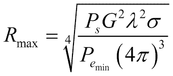
In relation to a specific radar system, most quantities (Ps, G , λ) can be regarded as constant, since they are only variable device data in small areas. On the other hand, the reflecting surface σ is a size that is difficult to grasp and is therefore usually assumed to be a practical value of 1 m²
Under this condition, the received power PE is of interest, which causes an echo signal in the radar receiver that is just barely perceptible. This received power is called PE min. Smaller receiving powers cannot be used because they are lost in the noise of the receiver. Inserting PE min into the radar equation means that the theoretical maximum range R max can be determined with the equation.
A practical application of this radar equation is the determination of performance data for certain radar systems with the aim of comparing and evaluating the systems.
Influences on the range of a radar system
All considerations in connection with the radar equation have so far been made under the assumption that the electromagnetic waves can propagate under ideal conditions. In practice, however, there are a number of losses that cannot be ignored, since they reduce the effectiveness of a radar system, in some cases considerably.
For this purpose, the radar equation is first expanded by the loss factor L tot.
This factor summarizes the types of losses listed below as examples:
- LD = device-internal attenuation losses on the transmission and reception path
- L f = fluctuation losses in reflection at the target
- L Atm = Atmospheric attenuation losses on the propagation path to the target and back
Device-internal attenuation losses arise mainly from high-frequency components such as waveguides, filters, but also from a radome. This type of loss is relatively constant in terms of its value in relation to a specific radar system and can also be easily determined (measurable).
Atmospheric attenuation and reflections on the earth's surface are a constant influence .
Not every transmission tube is the same: minimal manufacturing tolerances can affect the achievable transmission power and thus also the theoretical range. But as a reminder: the transmission power is under the 4th root!
So we have to increase the transmission power sixteen times just to double the range!
Deviations in the specified range are certainly also understandable: if, for example, the transmission power of the P-12 can vary from 160 kW to 250 kW (permissible), can the different specified range of 250 to 270 km also be correct?
And that only taking into account the transmission power.
In practice, values between 180 kW and 240 kW were achieved because the transmission power of the disc triode was also frequency-dependent (hence the large tolerance range!).
The reverse conclusion is also permissible: if (e.g. due to the failure of one of sixteen transmitter modules) the transmission power is reduced by one sixteenth, then the influence on the range of the radar station is actually negligible in practice (range loss < 2%):
The minimum reception power is different from the transmission power: It is also under the 4th root, but in the denominator. A reduction in the minimum reception power of the receiver increases the range.
There is a certain reception power for each receiver, from which it can work at all. In radar technology, this smallest processed received power is often given the designation MDS - Minimum Discernible Signal. MDS echo sizes typical of radar are in the range of -104 dBm to -110 dBm (measurement method).
The antenna gain G is even squared under the 4th root. We remember: the antenna is also used on the way there and back. Thus, quadrupling the antenna gain will result in a doubling of the range. And again a practical example from meter wave technology:
The P-12 ( Yagi antenna : G=69) was sometimes operated on the antenna of the P-14 ( parabolic antenna: G=900). This combination was often jokingly called "P-13". According to our radar equation, the following gain in range should result:
But the much larger antenna also required much longer feed lines. These losses and the radiator mismatch eat up more than half of the gain in range.
Nevertheless: the fold range was not to be scoffed at either. Only now increasingly disturbing overreach occurred. Depending on the type of information desired, the radar devices must have different characteristics and technologies. Based on these properties and techniques, they are divided into:
Primary radars emit high-frequency signals that bounce off targets. The resulting echoes are received and evaluated. This means that, in contrast to secondary radar devices, primary radar devices receive their own transmitted signals as an echo.
These radars require the aircraft to have a transponder (replay transmitter) on board and will receive a coded signal from the radar. An active response is generated in the transponder, which is then also sent back in coded form to the radar device. This response can then contain much more information than a primary radar device can work out (e.g. flight altitude, identification or technical problems on board, such as radio failure... ).

Pulse radar devices emit a pulsed, high-frequency, high-power signal. This is followed by a longer pause in which the echoes can be received before a new transmission signal is sent out. The direction, distance and, if necessary, the height of the target can be determined from the position of the antenna and the propagation time of the signal.
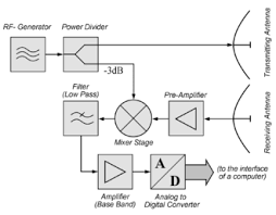
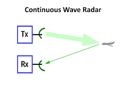
Continuous wave radars or CW radars continuously emit a transmission signal. The echo signal is continuously received and processed. The receiver does not necessarily have to be in the same place as the transmitter. Any powerful broadcast transmitter can also function as a radar transmitter if a remote receiver compares the transit times of the direct and reflected signals. Tests are known from the USA that the exact location of an aircraft can be calculated from the evaluation of the signals from three different television stations. ( bistatic radar)
Unmodulated Continuous Wave Radars
The transmission signal from these devices is constant in amplitude and frequency. These devices specialize in speed measurements. Distances cannot be measured. They are used by the police , for example, to measure traffic . The latest devices ( LIDAR ) work in the laser wave range and not only measure the speed. By the way: Flitzer speed cameras are also available for pilots!
Modulated continuous wave radars
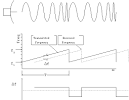
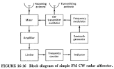
The transmitted signal has a constant amplitude, but is modulated in frequency (frequency modulated continuous wave radar). This makes it possible again to determine the distance based on the principle of transit time measurement. The distance (=height) can then be determined from the frequency shift. The advantage of these devices is that an evaluation takes place without a break in reception and the measurement result is therefore continuously available. They are used wherever the measuring distance is not too great and continuous, uninterrupted measurement is important, eg when measuring flight altitude in aircraft or in weather radar as a " wind profiler ".”. A similar principle is also used by radar devices whose transmission pulse is too long to achieve good range resolution. These often additionally modulate their transmission pulse in order to use pulse compression to also determine the distance within the transmission pulse.
With a bistatic radar device there is a greater distance between the transmitter and receiver and usually also a greater azimuth deviation . A signal is therefore also received if, due to the geometry of the reflecting object, no or only very little energy ( stealth technology !) is reflected in the direct direction of a monostatic radar.
The primary radar device has one essential property: it works with passive echoes. The emitted high-frequency transmission pulses are reflected by the target and then received again by the radar device. The direct cause of the reflected echo is therefore the transmission pulse sent out by the radar device.
Secondary radars work on a different principle:
They work with active response signals. The secondary radar device also sends high-frequency transmission pulses, the so-called interrogation ( interrogation ). However, this is not simply reflected, but received by the target and received and processed by means of a response device ( transponder ). Then, with a different frequency, an answer, the answer telegram is generated and transmitted.
Both systems have different advantages and disadvantages due to the different principles. If one gains reliable information about the direction, height and distance of the targets with the primary radar, the secondary radar provides additional information such as identifier, identification and also the height of the targets.
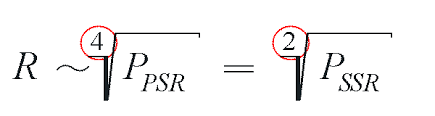
However, as already mentioned, the cooperation of the target (transponder) is necessary. On the other hand, it is precisely through this active cooperation of the target that a drastic reduction in the transmission power can be achieved at the same distance, since this is included in the radar equation with the outward and return path in the case of primary radar, but only with the outward path in the case of secondary radar.
A factor > 1000 can be assumed here as a guide value. The result is a considerably simpler, smaller and cheaper transmitter. At the same time, the receiver can be less sensitive since the power of the active responses is higher than that of the passive echoes.
However, this circumstance has a disadvantageous effect on the influence of sidelobe reception , which must be compensated for by suitable sidelobe suppression measures .
Due to the different transmission and reception frequencies, there are no MTI interferences . This means that all measures to suppress fixed targets are no longer necessary.
On the other hand, a frequency change is impossible when the frequency is disturbed. Special disturbances in secondary radar systems make additional switching measures in the devices necessary.
Since the receiver of a secondary radar device does not have to be as sensitive as that of a primary radar device, the focus of the interference is on the impulse interference. A technician would classify the glitches into synchronous and non-synchronous glitches. But since operators called Controller sit at the viewing devices, the disturbances are picturesque as:
designated. In addition, of course, there are also disturbances that are not impulses. However, these are usually only combated by automatically reducing the receiver sensitivity and by displaying a flashing signal lamp ("jamming").

Timing control of a pulse radar device
The pulse repetition frequency ( Pulse Repetition Frequency PRF) of a radar device determines how often a high-frequency pulse is emitted per second. Since you have to wait for incoming echoes in the time between the transmission pulses, this frequency must not be too high for long-range radar devices so that the receiver has enough time to also receive echoes from distant aircraft. The pulse repetition frequency therefore influences the theoretically maximum measurement distance.
The reciprocal of the PRF is the Pulse Repetition Time , sometimes called the Pulse Repetition Period.
After the transmit pulse, there is a recovery time ts, mainly for the transmit/receive switch . Only after this time will the receiver blocked during the transmission time be operational again. The transmission time and the recovery time determine the minimum measuring distance of the radar device.
The incoming echo signals are processed in the following reception time Te. This time could last until the next transmission pulse, but in practice it has proven useful to switch off the receiver a little earlier and insert a dead time . This prevents extremely distant, but nevertheless very strong echoes from a PRT from being displayed as false targets (overranges similar to superrefraction ) in the following PRT with the wrong distance. In more modern radar devices, this time is used to complete internal test routines.
Willkommen bei den Webseiten von Roman Nikolaus Urban
